
Removing from the box
Obviously a hoist is needed to get this job done safely. Lycoming say:
_The hoist must have a capacity to lift a minimum of 750 lb (340 kg)_
Must be a safety factor, since the engine weighs not much over 300lbs ??
Our engine was encased in foam, so we ended up cutting/tearing off the cardboard and lifting it with the foam still attached.
We lifted the whole package, base unit included …
… and placed it carefully on my trusty workbench.
Then we removed the foam from the rear to enable attachment of the various items before installing in the aeroplane.
Fittings
There are several pipe fittings which are best installed prior to installing the engine.
A few involve clocking, and best angles are depicted in the Vans manual.
This is the Lower Oil Port, and we temporarily attached its hose to check it could be installed without interference with the Vernatherm lower nut.
The Upper Oil Port is an AN816-8D. Since this is a straight fitting and therefore doesn’t involve clocking, we actually installed this first to “find our feet”!

Bear in mind the fittings and clocking angles are different on the 14A nosewheel installation!
This means the manual has to be carefully read, as always.
Lots of these port holes arrived from Lycoming with blanking plugs installed, covered in paint.
After removing the plug, this is the Oil Pressure fitting, a VA-128. These pressure fittings have a restrictor incorporated to reduce pressure fluctuations.
This shows the fittings on the engine driven fuel pump, in the lower portion of the picture.
Here is the Oil Temperature Sensor.
This has a copper washer underneath, and the installation leaflet advises about one further turn from snug to squash the washer slightly.
Standby Alternator
We are fitting a BC 410-H Spline-Drive Alternator as a secondary, and this meant we had to specify the rear accessory drive was installed on our EXP119 engine.
The B&C manual advises preparing the gasket with Hylomar.
To avoid any head scratching, we had removed the right PMag in this picture, and temporarily attached the blanking plate from the left side … the engine arrived with only the right PMag installed (see later).
Due to the constraints on the engine casing, there were only two orientations of the alternator to choose from … and we chose this way.
It was quickly clear that torquing of the lower left nut was going to be a big problem …
… unless you have a friendly engineer mate who has just the right tool!
This clever spanner made the job easy and accurate.
Without a tool such as this it would be difficult even with a crowsfoot.
Talking of torque settings … they are all sprinkled liberally over several different manuals, especially the Lycoming documentation.
If I was doing this again I'd spend time beforehand extracting all the various values and listing in a reference document for easy retrieval!
PMags
I think Lycoming may have changed their policy now, but at the time we purchased the engine they would not install a second PMag.
So we had specified a blanking plate on the left mag position, with studs the correct length for another PMag (apparently an impulse mag has larger studs which would need changing prior to installation of a second PMag).
Lycoming supplied a cog ready to be installed on our separately purchased PMag.
It was quite a fiddle to fit the cotter pin due to the hole being inside the “well”. It is important that the cotter pin is pressed flush with the top of the stud, or there is a risk it may rub on the engine accessory face.
Lycoming suggest high temperature grease is applied to the magneto flanges, but E-Mag don’t specify this … probably because they will not need rotating during timing.
Anyway our engineering mate had some, so we smeared some on the gaskets anyway.
We thought it easiest to have a good guess at the required PMag orientation, and to torque up prior to installing the engine.
But if they have to be adjusted it won’t be too hard a job after the engine is installed.
As you can see in the picture, we also installed the manifold pressure tubes onto the little nipples on the rear face of the mags whilst we could easily reach.
Dipstick & Grounding Braid
There is no mention in the various manuals of when to install the dipstick, but having looked at the geometry we reckoned it wouldn’t get in the way during installation.
Since access is easier for wirelocking at this stage, we went ahead and fitted it, together with the grounding strap.
The grounding strap needed some paint to be removed from the precious engine, otherwise it won’t ground properly. Since this takes the starter current it’s quite important!
Ready to go!
After a few hours work we had everything attached and torqued, ready for the big moment.
Installation
Before hanging the engine on the front, we thought it prudent to secure the tail. Tim had found an old 56lb weight which should do the trick!
You nosewheel builders won’t have this problem : )
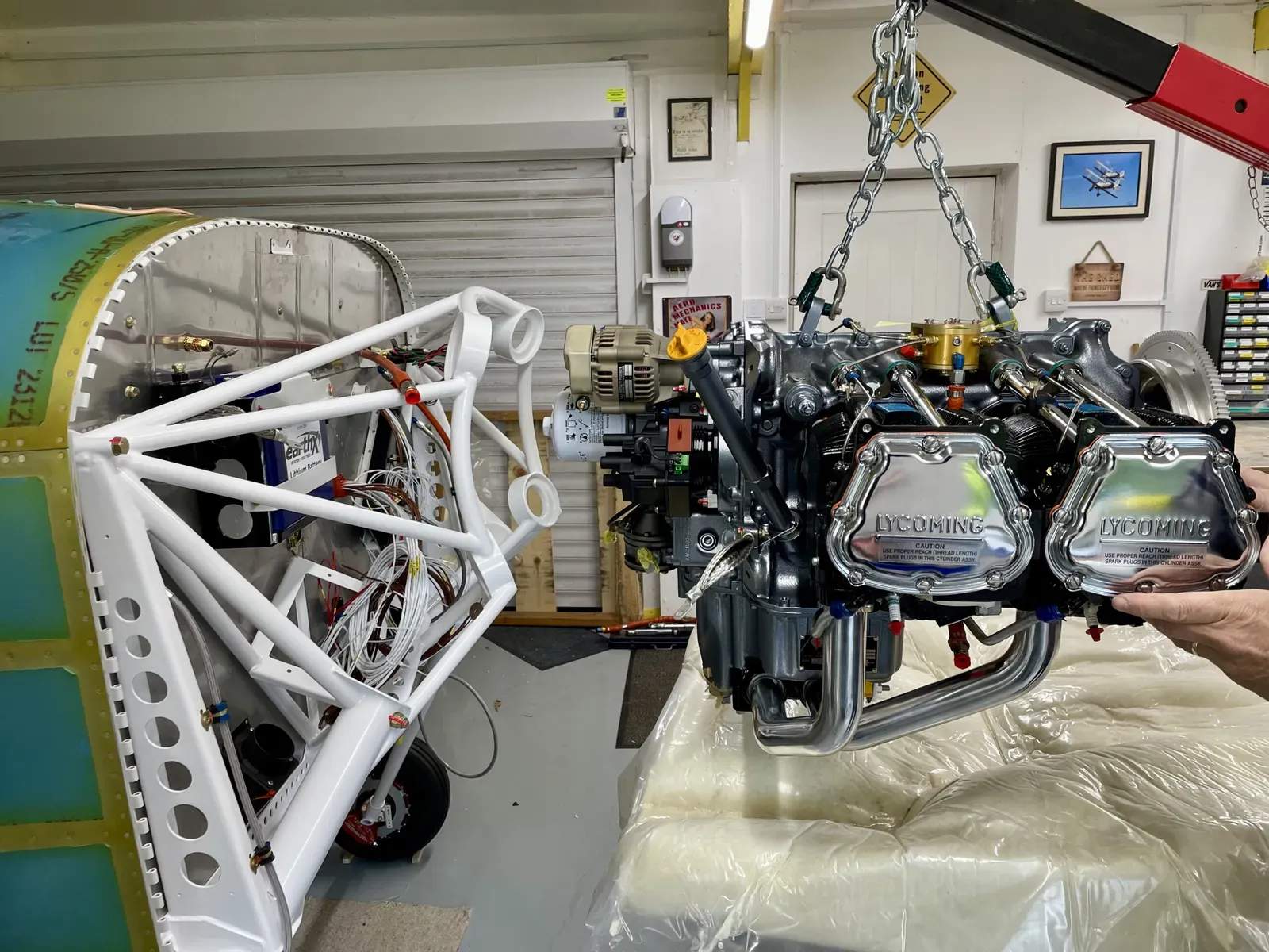
After removing the rest of the packaging foam, we lifted it off the bench and could see the engine in all its glory for the first time.
Not that we didn’t trust the hoist, but we couldn’t resist a safety table underneath in case of disaster : )
Here’s the engine being carefully moved into position. It needed to be slightly low at first in order to get the standby alternator inside the engine mount.
The actual fitting went very smoothly, only taking about 50 mins!
We got the top bolts in first, then the lower right. The lower left needed a few wiggles of the engine, but even that one located before too long.
We have heard stories of hammers and tyre levers being employed at this stage, but are happy to report that no Lycoming engine was injured during our installation : )
The rubber engine mounts have to be located in a certain way, since one of each pair is harder than the other … all explained in the Vans manual. The lower ones also have a washer between them and the engine, easily missed.
Anyway, after a “high five”, we celebrated by heading out for lunch!
Another milestone : )